
README.md
LM21305-Based Power Distribution Board
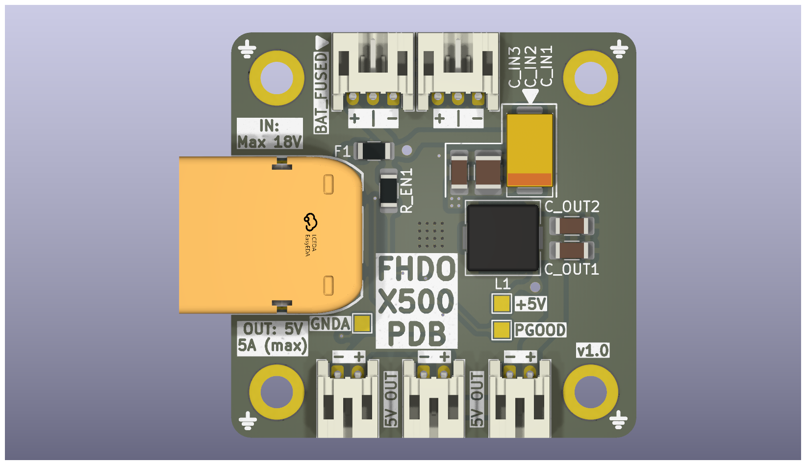
Overview
This project describes a compact power distribution board (PDB) for multicopter applications. The design is based on the LM21305 synchronous buck regulator and provides regulated 5 V outputs alongside direct battery connections.
The board follows a 30 × 30 mm mounting pattern, compatible with standard flight controller stacks.
Features
- LM21305-based DC-DC regulation
- 30 × 30 mm mounting pattern
- Maximum output current: 5 A
- 3 × regulated 5 V outputs (JST-PH 2.0)
- 2 × battery outputs (JST-PH 2.0)
Specifications
| Parameter | Value |
|---|---|
| Input Voltage | 3 V – 18 V |
| Regulated Output | 5 V |
| Maximum Current | 5 A (total) |
| Mounting Pattern | 30 × 30 mm |
| Connectors | JST-PH 2.0 |
LM21305 Regulator Summary
The LM21305 is a synchronous step-down (buck) DC-DC converter with integrated power MOSFETs and peak current-mode control. :contentReference[oaicite:0]{index=0}
Key characteristics:
- Input voltage range: 3 V to 18 V
- Output current capability: up to 5 A
- Adjustable switching frequency: 300 kHz to 1.5 MHz
- Integrated high-side and low-side MOSFETs
Functional features:
- Peak current-mode control for fast transient response
- Internal soft-start and enable control
- Cycle-by-cycle overcurrent protection and thermal shutdown
- Overvoltage and undervoltage protection
These characteristics enable high efficiency and compact external component selection.
Electrical Interfaces
5 V Outputs (3×)
- 5 V
- Ground
Battery Outputs (2×)
- VBAT
- Ground
Mechanical Details
- Mounting hole spacing: 30 mm × 30 mm (M3 compatible)
Contributions
Contributions and issue reports are welcome.